Advanced Versions
The information here is for the base version of our Pick-to-Light system. For advanced versions please Contact Us
Structure of the System
Introduction
Pick-to-Light is used primarily in warehouse and distribution center operations to optimize order picking and kit assembly processes. Our Pick-to-Light solution consists of a Pick-to-Light Gateway and a number of Pick-to-Light Nodes.
This guide provides information on the operation and features of our Pick-to-Light system.
Main Features
Pick-to-Light Gateway
The Pick-to-Light Gateway is the control device of the system. The gateway has Modbus RTU and Web interfaces. The gateway communicates with Nodes via Modbus RTU interface. The Web interface of the Gateway is used to control the system. You can log in to the web interface as user or administrator. When logged in as an administrator, Gateway and Nodes can be configured, and recipes can be created and run. When logged in as a user, the recipes can only be viewed and executed.
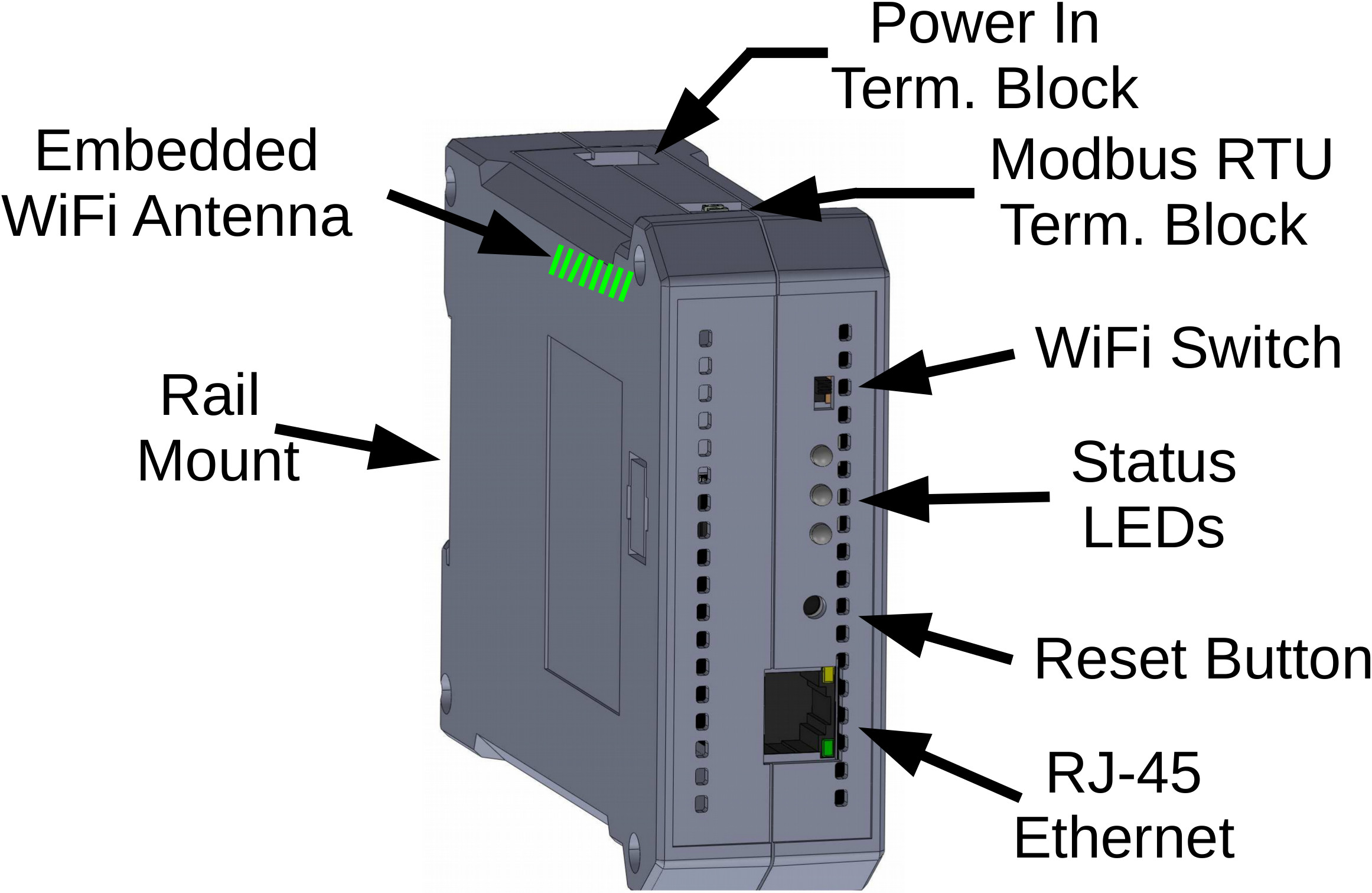
For more information please refer to the technical details page of Pick-to-Light Gateway
Pick-to-Light Node
The Pick-to-Light Node has a Modbus RTU interface. This interface is reached by 4 pin GX12 male connectors located on both sides of the device. 2 pins of GX12 connectors are used for Modbus RTU, 2 pins are used for ground and 12~24VDC power.
The nodes have a 3-character 7-segment LED display, RGB light signal button and optical sensor to interact with the user. The Gateway can detect whether the user triggers the button or optical sensor.
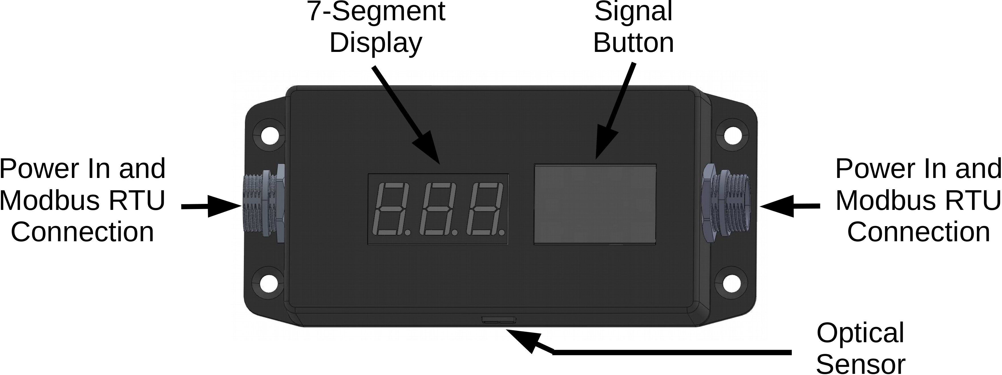
Each node has one "Device ID" and one "Common ID". The "Device ID" must be unique for each device in a system. The "Common ID" must be common across all devices in the system. The default device ID and common ID for a device are "1" and "195", respectively. Both IDs can be changed via Gateway upon request.
For more information please refer to the technical details page of Pick-to-Light Node
Pick-to-Light Mini
The Pick-to-Light Mini is an alternative to Pick-to-Light Node. Pick-to-Light Mini has compact size and its ergonomic design ensure seamless integration into diverse picking environments.
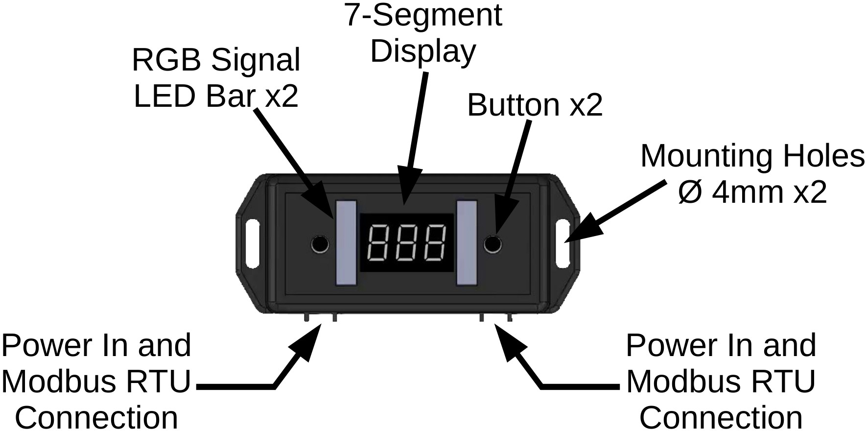
Pick-to-Light Mini features a 3-character 7-segment LED display, RGB LED indicators and tactile buttons. With these feature it offers intuitive guidance and interaction for workers. The customizable color options of the LED enable clear communication of instructions or status updates. The tactile buttons allow for effortless confirmation of picks and triggering of actions.
For more information please refer to the technical details page of Pick-to-Light Mini
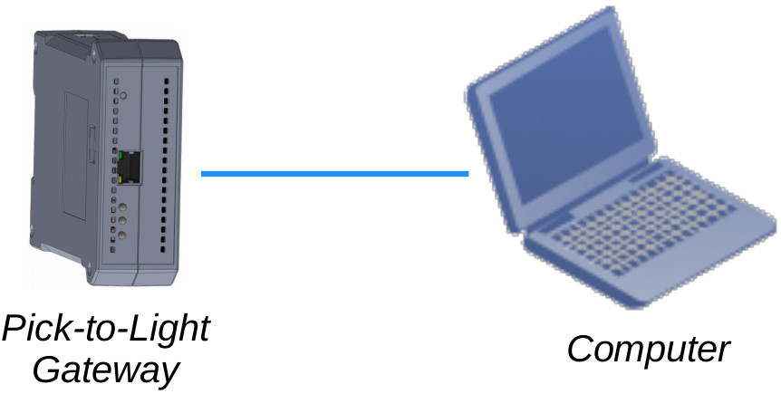
Connection
To configure, please prepare the following items:
- Pick-to-Light Gateway
- A computer with a wired network and a web browser.
- Ethernet cable
- 12 or 24VDC 2A power supply
- Set the computer's wired network connection according to the parameters given below:
- Connect the computer directly to Pick-to-Light Gateway.
- Open to the web interface Pick-to-Light Gateway: http://192.168.10.55
| IP | 192.168.10.2 |
| Netmask | 255.255.255.0 |
| Gateway | 192.168.10.1 |
Warning
The instructions here are for a device with default settings.
To load the default settings to Pick-to-Light Gateway, press the "Reset" button which is at the front of the device for about 3 seconds (until the blue and orange lights flash). Then release the reset button and wait for the device to reboot.
Web Interface Layouts
There two different web interface layouts for admin and user.
Admin Web Layout
There is one main panel in the administrator's web interface. Administrator can use the buttons in this panel to navigate along the settings.
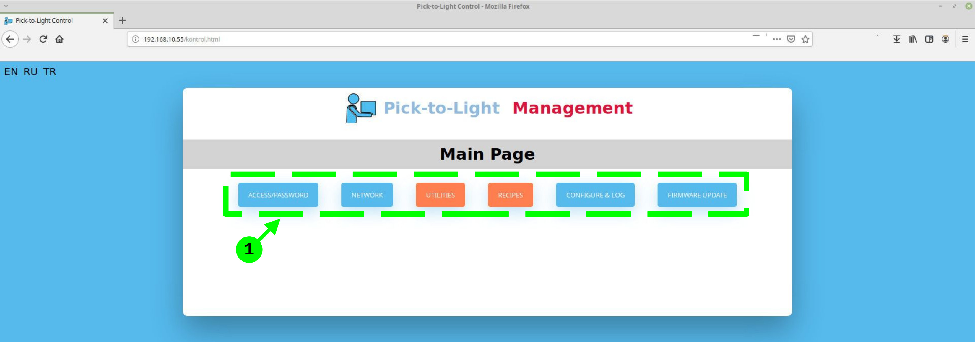
- Button set for panel display selection
- For Pick-to-Light Gateway Access/Password configuration: Access/Password
- For Pick-to-Light Gateway Network configuration: Network
- For Pick-to-Light related (such as ID, Light Color, etc.) configurations: Utilities
- For Recipe/Workorder Configuration: Recipe
User Web Layout
There are five panels in the user's web interface.
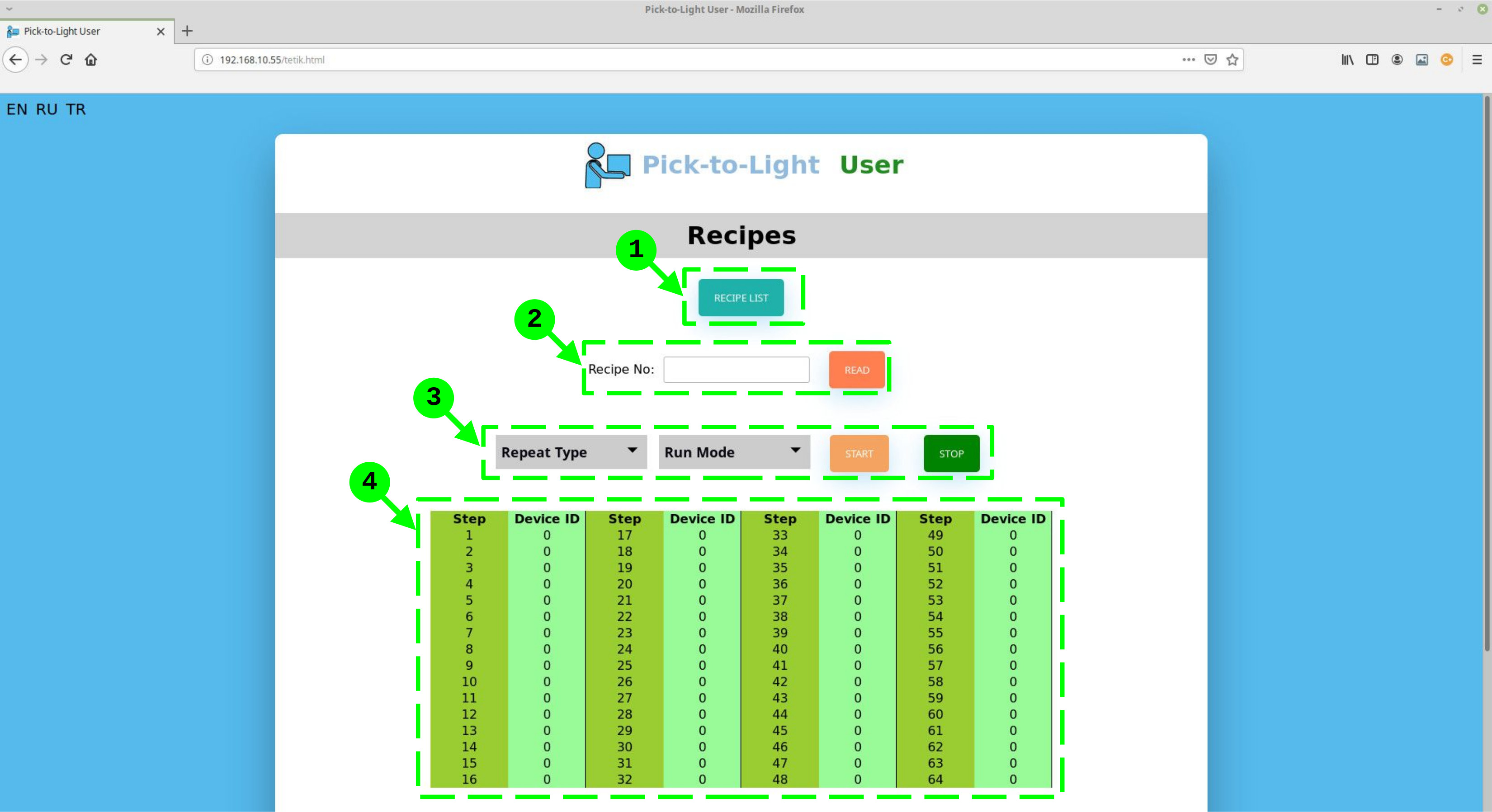
- Recipe/Workorder List Dialog Button
- Recipe/Workorder Query Area
- Recipe/Workorder Execution Area
- Recipe/Workorder Detail Area
User can use this button to open Recipe List dialog box, where the list of recipes/workorders are displayed.
User can query recipe/workorder by using this area.
User can select execution mode of recipe/workorder
This area shows the details of the recipe/workorder.
Access/Password
Click to the "ACCESS/PASSWORD" button to change the user and administrator login name and password.
After changing the user and/or administrator name password, press the "Save" button.
Network
Click to the "NETWORK" button to change the network parameters, enable/disable the WiFi interface or enable/disable the WiFi access point option.
After changing the network settings, press the "Save" button.
Show ID
The Show ID button is used to show the device ID of the nodes on the 7-segment led display. After pressing the Show ID button, the name of the button changes to "Don’t Show ID". To end the display of IDs, the "Do Not Show ID" button must be pressed.
Set One ID
Set One ID is used to change the device IDs of nodes. When Set One ID button is pressed, the "Set One ID" dialog box is displayed on the screen.
With the "Set" button of "Set One ID" dialog box, a new ID is assigned to a device whose device ID is known. With the "Set to All" button of this dialog box, the device ID is assigned to an unknown device or all devices connected to the system.
Set ID Sequentially
The set ID sequentially button is used to change the device IDs of nodes by triggering devices sequentially. When Set ID Sequentially button is pressed, the "Set ID Sequentially" dialog box is displayed on the screen.
To set ID sequentially, the Common ID of the devices must be known. The Common ID is used to identify triggered devices. After typing the common ID in this dialog box, the first ID to be assigned to the devices and the last ID should be written. The last ID can be greater than or equal to the last device ID to be assigned.
After the common, first and last IDs are entered, the "Start" button is pressed to perform the assignment process and individual devices are triggered. Triggered devices will first have an error light and then the ID assigned to the device will be shown.
When the sequential ID assignment process is complete, the sequential ID assignment process is terminated by pressing the "End" button.
Check Device
The check device button is used to check the connections of devices in the system. When the check device button is pressed, the "Check Device" dialog box is shown on the screen.
In the check device dialog box, the IDs of the first device to be checked and the last device to be checked are entered. Then the "Start" button is pressed. The gateway sequentially sends show ID command to individual devices within the entered range, making devices to show their IDs.
The "Finish" button is pressed to end the device inspection process.
Light Setup
The light setup button is used to change the status lights and texts of nodes. When the light setup button is pressed, the "Light Setup" dialog box is shown on the display.
In the light setup dialog box, the ID of the device to be adjusted is written in the "Device ID" field and the "Status" to be adjusted is selected and the "Read" button is pressed.
Each node can be in 3 different states. These states are given in the following table.
| STATE | EXPLANATION |
|---|---|
| JOB | Used to show that the device has "work" according to the recipe. |
| DONE | Used to show that work has been done (the device triggered) according to the recipe. |
| ERROR | Used to show that the device is triggered not according to the recipe. |
Nodes can indicate their status separately with one of 13 different colors. These colors are Green, Red, Blue, Yellow, Orange, Amber, Cyan, Purple Pink, Rose Pink, Lime Green, Spring Green, Purple, Sky Blue and White.
In addition, text indication can be made for the "Job" state. This text is shown on the 7-segment led display when the device is set to "Work" state within the scope of the recipe.
After configuring the selected state of the desired device, the "Write" button is pressed to transfer the update to the device.
Modbus
Advanced settings of nodes can be made via the Modbus RTU interface. When the Modbus button is pressed, the "Modbus" dialog box is displayed on the display.
To read the register, the device ID of the desired node is entered in the Modbus dialog box. Then the register address range to be read is written and the "Read" button is pressed. When the read operation is performed, the values are shown in the "Reg" boxes respectively. To perform the write operation, these values are changed optionally and the "Write" button is pressed.
| REGISTER | DESCRIPTION |
|---|---|
| 1001 | Device ID |
| 1002 | Common ID |
| 1003 | Optical Trigger threshold value |
| 1004 | Common ID trigger status |
| 1005 | Common ID the triggered device ID. Same as "1001" device IDD |
| 2001 | Job led color |
| 2002 | Done led color |
| 2003 | Job text start register |
| 2101 | Error led color |
| 3001 | Device state |
| 3002 | Test state |
| 4000 | Return to Factory Defaults |
Add/Delete/Update
Press the "Recipe List" button to view the recipes stored in the Gateway.
On the recipe list dialog box, you can add, delete and change the name of the recipe, and write a description about recipe.
After updating the recipe list, the changes are sent to the Gateway by pressing the "Save" button.
Press the "Add" button to add a new recipe to the recipe list. In the recipe list, the new recipe is created with the first "Number" in the sequence and with the default name and description.
To delete a recipe, click on the recipe and then press the "Delete" button.
Read/Update/Train/Operate
To read a recipe, type "Recipe No" on the "Recipes" page and press "Read". After reading, the recipe steps will be displayed in the recipe table.
You can check the "Recipe List" to find out the recipe number.
To update the recipe steps, go to the device ID of the desired step and write the desired device ID to the "Device ID" column in the table. Press the "Write" button to save the update to the gateway.
Recipe steps can be entered individually through the web interface of the gateway or through devices. To do this, press the "Teach" button and trigger the device with the button or optical sensor you want to work in the step in the recipe. The ID of the triggered device is retrieved by the gateway and written to the device ID line. With this method, the desired devices can be triggered sequentially and the recipe can be defined. After the training process is completed, press the "Write" button to save the recipe.
To run a recipe, the two run features should be chosen. These are "Repeat Type" and "Run Mode". The repeat type can be selected as "Single" or "Repeat". The operating mode can be selected as "Sequential" or "Batch".
After the recipe run features are selected, press the "Start" button. The recipe is being executed from the first step and ends with the first device ID "0". The recipe run process can be terminated by pressing the "Stop" button.
Executing Recipe
When logged in as the user, only the recipe list can be viewed and recipe reading and run operations can be performed.
Press the "Recipe List" button to view the stored recipes. The recipe list will be displayed on the screen with the recipes stored on the gateway.
To read a recipe, the number of the desired recipe is written and the "Read" button is pressed. After the recipe reading process, the recipe steps are displayed in the recipe table.
To run a recipe, the two run features should be chosen. These are "Repeat Type" and "Run Mode". The repeat type can be selected as "Single" or "Repeat". The operating mode can be selected as "Sequential" or "Batch".
After the recipe run features are selected, press the "Start" button. The recipe is being executed from the first step and ends with the first device ID "0". The recipe run process can be terminated by pressing the "Stop" button.